

Home > News
News
-

Over Voltage Protection Device-Varistor Selection Rule
Over Voltage Protection Device-Varistor Selection Rule When it comes to selecting the MLV for designing within the circuit, some characteristic parameters should be considered carefully to meet the circuit condition. Please see the recommended guideline below. 1.While choosing the MLV, the working voltage of the MLV should be greater than or equal to the normal operating voltage of the circuit. 2.Surge (or ESD) handling ability of the selected MLV should meet need for dissipating the expected transient surge current (or ESD voltage) of the protected circuit. 3.The clamping voltage of the selected MLV should be less than maximum allowed operating voltage of the protected circuit. 4.In the high speed data transmission situation, capacitance of the selected MLV should be considered. [View Details] -
Over Voltage Protection Device-Voltage Dependent Characteristic
Over Voltage Protection Device-Voltage Dependent Characteristic Voltage Dependent Characteristic Transient Voltage Suppressors (Varistors) are voltage-dependent electrical resistors with symmetrical V/I characteristic and the breakdown region, their resistance value decreases with increasing voltage, thus “short – circuiting” further rises in over voltage. The Prevention of Over Voltage In other words, as long as the voltage increases above the threshold of the TVS, the suppressor will draws a rapidly increasing current, and then the over voltage is considerably attenuated away from the protected circuit, that is why the inherent protection of the equipments should be supplemented by including specific components that will raise the withstand capabilities to the required level. Varistors provide protection against all kinds of over voltage and prevent electronic equipment from being damaged by transient events. [View Details] -

Over Voltage Protection Device-SMD Transient Voltage Suppressors
Over Voltage Protection Device-SMD Transient Voltage Suppressors Product Introduction Product Feature * Full range from 0201 to 2220 series * Working voltage from 2.5 to 300 Vrms; 3.5 to 385 Vdc * High surge current ability * Bidirectional clamping, high energy * Fast response time * Suitable for ESD protection * Array type design * Very low leakage current * Good solderability Product Series MLC series: Multilayer surface mount for wide range applications. MLA series: Multilayer surface mount design for high energy and surge application. ESD series: Low capacitance design for high data transmission. CH series: Mono layer surface mount design for high voltage suppressor, the working voltage could be up to 385Vdc. Major additions and improvements: Multilayer Surface Mount Transient Voltage suppressors (TVS) are manufactured from semiconducting ceramics by the highly advanced multilayer formation technologies, which can offer rugged protection, excellent transient energy absorption and internal heat dissipation. The devices are leadless chip form, eliminating lead inductance and guaranteeing a faster speed of response time of less than 0.5ns, which makes them fast enough to ensure reliable protection against ESD pulse and other specific transient events. These transient suppression devices are significantly smaller footprints and lower profiles than traditional zener diodes or radial Metal Oxide Varistor. Material: Body material: ZnO Termination: All size from 0201 to 3225. All Nickel Barriers (Ag/Ni/Sn) Products are RoHS compliant. [View Details] -

Influence of aging on electrolytic capacitors function in static converters Fault prediction method
Influence of aging on electrolytic capacitors function in static converters: Fault prediction method The failure of electrolytic capacitors is the cause of most breakdowns of static converters. The function of these capacitors is to filter and to store electrical energy. Accelerated aging tests showed that the increase of the internal resistance ESR of the capacitors is a good indicator of their faulty state. The filter function is affected by the capacitors wearout on the one hand. At high frequency, the voltage ripple at the terminals of the capacitors increases according to ESR rise. On the other hand, the storage function is not much influenced by the capacitors aging. As static converters work most of the time at variable load, high transient values of the voltage ripple occur when output current changes that can induce false alarms. These transients are verified theoretically and experimentally. In order to avoid these transients effects, we suggest to monitor the fundamental component of the voltage ripple. This latter waveform is the best signature of the capacitors state. The ESR of the capacitors and the time before their failure are deduced from the processing of this waveform with other converter parameters such as input voltage, output current and ambient temperature. [View Details] -
 Safety Capacitors
Types of Safety Capacitors:
•There are two major types of interference-suppression/AC line filter safety capacitors; namely, type X and type Y. The purpose of these capacitors is to reduce radio frequency interference and to ensure safety from shock and fire.
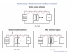
•In addition to helping to block out noise interference from being received, they are also used in electrical devices and appliances to help prevent noise interference from being sent out. Below is a schematic of a modern day “line filter circuit” which shows the safety capacitor(s) C1 and C2. Capacitor C1 would be a type X “across the line” capacitor and the two C2s would be type Y “line to ground” safety capacitors.tem
•Class X capacitors are used in “across-the-line” applications where their failure would not lead to electric shock. Class X safety caps are used between the “live” wires carrying the incoming AC current. In this position, a capacitor failure should not cause any electrical shock hazards, rather, a capacitor failure “between-the-lines” would usually cause a fuse or circuit breaker to open.
•Class Y capacitors are used in “line-to-ground” (line bypass) applications where their failure could lead to electric shock if a proper ground connection were lost. The failure of a “line-to-ground” capacitor would not open any safety fuse. In other words, the failure of a line bypass capacitor could create a 120 volt “hot” chassis that could give you a potentially fatal shock.
•Because the terms X and Y are pretty non-descript, it can be hard to remember which type go where. To remember, just think of the X as being A CROSS on a 45 degree angle, and there you have it ….X is for “A CROSS the line” applications.
•Most safety capacitors have voltage ratings of 250 VAC and can be used in circuits up to 250 VAC.
Classes of Safety Capacitors:
•Safety capacitors are grouped into a number of different classes. For X Type capacitors there are class X1, X2 and X3. For Y Type capacitors there is class Y1, Y2, Y3 and Y4.
•The only types you will probably see for sale are X1 (impulse tested to 4000 Volts), X2 (tested to 2500 V), Y1 (tested to 8000 V) and Y2 (tested to 5000 V).
•Of the above capacitors, type X2 and Y2 are the most popular and the type that you will probably want to use. X2 and Y2 safety capacitors are used in appliances that plug into ordinary household wall outlets, while type X1 and Y1 are for heavy duty industrial use. For example, a type X1 capacitor would be used in an industrial computer or industrial lighting ballast that is connected to a 3-phase line (the main power truck lines within a building).
•You could use type X1 and Y1 in your tube electronics if you wanted to, but all you require to meet safety standards is the X2 and Y2. The type 1’s will cost you more money and may be more difficult to install due to their larger size.
•Are X2 and Y2 capacitors interchangeable? Yes and no! You can safely use an Y2 capacitor in place of an X2 capacitor for an “across-the line” application, but you should not use an X2 capacitor in place of an Y2 capacitor for a “line to ground” application. The X2 type would work and remove noise interference, but would not meet line-to-ground safety standards. This is because Y2 capacitors are more robust, take higher test voltages and are designed to open, (rather than short) should a failure occur.
•What do Y2 safety capacitors have in common with your cars windshield? They are both built “not to break” and if they do break, they are built to “break safely”.
•By now you are probably asking yourself…if Y2 capacitors are so great and can be used for X2 purposes … why not just forget about X2 capacitors and use Y2 type all the time? There are two good reasons … cost and size. Y2 safety capacitors are more expensive than X2 type and Y2 capacitors are larger (which can may make installation harder). Using Y2 type capacitors when an X2 type is all that is required would be like re-capping your tube radios with 1600 volt capacitors rather than 630V caps. All you have done is spent more money that you had to.
•Once in a while you will see a safety capacitor that is a combination of X and Y classes. For example, an X1/Y2 ceramic disc safety capacitors. This simply means that the capacitor meets safety qualifications as both an X1 capacitor and an Y2 capacitor. If I might use a car analogy again, you might think of an X2 capacitor as a special summer tire, an Y2 as a rugged winter tire and an X1/Y2 as a versatile all-season tire.
Construction of Safety Capacitors:
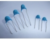
•Safety capacitors are available in ceramic disc and metalized film or paper. The film type are made of self-healing metalized polyester, polypropylene or paper and usually come in a “box” style casing as the capacitor is encased is a flame retardant or flame-proof case.
•Ceramic disc safety capacitors have the advantage of being economically priced and compact in size (making installation easy). One limitation ceramic disc safety caps have is that the largest uF capacitance size available is 0.01 uF (which is sometimes lower than what is needed per the schematic). If you require Y2 safety capacitor that has a capacitance over 0.01uF you will need to use Y2 capacitor made of Poly Film.
•Type X2 film capacitors are also very economical, are relatively compact and are available in a wide range of sizes.
•Y2 film capacitors are more expensive and larger that both disc capacitors and X2 film capacitors. Most film capacitor manufacturers make Y2 capacitors up to 0.047uF maximum.
•All safety capacitors should have certifier’s symbols on their casing. For example UL (for USA), CSA (for Canada), VDE (for Germany), etc. To ensure you are using properly certified safety capacitors check that certification symbols (see below) are on the cases.
•There are also certain safety standards/certification tests that you want the capacitors to meet. For Radio, TV and certain other telecom use the requirement the standard that should be met is: UL1414 (USA); CSA C22.2 No.1 (Canada) and EN132400 (Europe). [View Details]
Safety Capacitors
Types of Safety Capacitors:
•There are two major types of interference-suppression/AC line filter safety capacitors; namely, type X and type Y. The purpose of these capacitors is to reduce radio frequency interference and to ensure safety from shock and fire.
•In addition to helping to block out noise interference from being received, they are also used in electrical devices and appliances to help prevent noise interference from being sent out. Below is a schematic of a modern day “line filter circuit” which shows the safety capacitor(s) C1 and C2. Capacitor C1 would be a type X “across the line” capacitor and the two C2s would be type Y “line to ground” safety capacitors.tem
•Class X capacitors are used in “across-the-line” applications where their failure would not lead to electric shock. Class X safety caps are used between the “live” wires carrying the incoming AC current. In this position, a capacitor failure should not cause any electrical shock hazards, rather, a capacitor failure “between-the-lines” would usually cause a fuse or circuit breaker to open.
•Class Y capacitors are used in “line-to-ground” (line bypass) applications where their failure could lead to electric shock if a proper ground connection were lost. The failure of a “line-to-ground” capacitor would not open any safety fuse. In other words, the failure of a line bypass capacitor could create a 120 volt “hot” chassis that could give you a potentially fatal shock.
•Because the terms X and Y are pretty non-descript, it can be hard to remember which type go where. To remember, just think of the X as being A CROSS on a 45 degree angle, and there you have it ….X is for “A CROSS the line” applications.
•Most safety capacitors have voltage ratings of 250 VAC and can be used in circuits up to 250 VAC.
Classes of Safety Capacitors:
•Safety capacitors are grouped into a number of different classes. For X Type capacitors there are class X1, X2 and X3. For Y Type capacitors there is class Y1, Y2, Y3 and Y4.
•The only types you will probably see for sale are X1 (impulse tested to 4000 Volts), X2 (tested to 2500 V), Y1 (tested to 8000 V) and Y2 (tested to 5000 V).
•Of the above capacitors, type X2 and Y2 are the most popular and the type that you will probably want to use. X2 and Y2 safety capacitors are used in appliances that plug into ordinary household wall outlets, while type X1 and Y1 are for heavy duty industrial use. For example, a type X1 capacitor would be used in an industrial computer or industrial lighting ballast that is connected to a 3-phase line (the main power truck lines within a building).
•You could use type X1 and Y1 in your tube electronics if you wanted to, but all you require to meet safety standards is the X2 and Y2. The type 1’s will cost you more money and may be more difficult to install due to their larger size.
•Are X2 and Y2 capacitors interchangeable? Yes and no! You can safely use an Y2 capacitor in place of an X2 capacitor for an “across-the line” application, but you should not use an X2 capacitor in place of an Y2 capacitor for a “line to ground” application. The X2 type would work and remove noise interference, but would not meet line-to-ground safety standards. This is because Y2 capacitors are more robust, take higher test voltages and are designed to open, (rather than short) should a failure occur.
•What do Y2 safety capacitors have in common with your cars windshield? They are both built “not to break” and if they do break, they are built to “break safely”.
•By now you are probably asking yourself…if Y2 capacitors are so great and can be used for X2 purposes … why not just forget about X2 capacitors and use Y2 type all the time? There are two good reasons … cost and size. Y2 safety capacitors are more expensive than X2 type and Y2 capacitors are larger (which can may make installation harder). Using Y2 type capacitors when an X2 type is all that is required would be like re-capping your tube radios with 1600 volt capacitors rather than 630V caps. All you have done is spent more money that you had to.
•Once in a while you will see a safety capacitor that is a combination of X and Y classes. For example, an X1/Y2 ceramic disc safety capacitors. This simply means that the capacitor meets safety qualifications as both an X1 capacitor and an Y2 capacitor. If I might use a car analogy again, you might think of an X2 capacitor as a special summer tire, an Y2 as a rugged winter tire and an X1/Y2 as a versatile all-season tire.
Construction of Safety Capacitors:
•Safety capacitors are available in ceramic disc and metalized film or paper. The film type are made of self-healing metalized polyester, polypropylene or paper and usually come in a “box” style casing as the capacitor is encased is a flame retardant or flame-proof case.
•Ceramic disc safety capacitors have the advantage of being economically priced and compact in size (making installation easy). One limitation ceramic disc safety caps have is that the largest uF capacitance size available is 0.01 uF (which is sometimes lower than what is needed per the schematic). If you require Y2 safety capacitor that has a capacitance over 0.01uF you will need to use Y2 capacitor made of Poly Film.
•Type X2 film capacitors are also very economical, are relatively compact and are available in a wide range of sizes.
•Y2 film capacitors are more expensive and larger that both disc capacitors and X2 film capacitors. Most film capacitor manufacturers make Y2 capacitors up to 0.047uF maximum.
•All safety capacitors should have certifier’s symbols on their casing. For example UL (for USA), CSA (for Canada), VDE (for Germany), etc. To ensure you are using properly certified safety capacitors check that certification symbols (see below) are on the cases.
•There are also certain safety standards/certification tests that you want the capacitors to meet. For Radio, TV and certain other telecom use the requirement the standard that should be met is: UL1414 (USA); CSA C22.2 No.1 (Canada) and EN132400 (Europe). [View Details] -
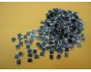
Safety Capacitors-Taping Specifications
Safety Capacitors-Taping Specifications Safety capacitor means for such occasions, that the failure of the capacitor would not lead to electric shock, do not endanger the personal safety. It includes the X capacitor and Y capacitors. x capacitance is connected across the capacitance between the two lines in the power line (LN), generally used in the metal thin film capacitor; The Y-capacitor is connected across the capacitance between the two lines and the ground of the power line (LE, NE), and generally occur in pairs . Based on the leakage current limit, the the Y capacitor value can not be too large, the general X capacitor uF level, Y capacitor is nF level. X capacitor differential mode interference suppression. The Y capacitor suppress common mode interference. [View Details] -
SMD Chip Varistor performance and specifications
SMD Chip Varistor performance and specifications Detailed Product Description 1.Approve:SGS,RoHS 2.Packing:tape/reel 3.Working Voltage from 2V to 36V 4.Wide operating temperature range from -55-125C high quality varistor description: Working Voltage from 2V to 36V Capacity from 0.15pf to 820pf Low cap design(0.2pf) for fast data transmission Fast response time(<0.5ns) Low leakage current High surge current ability Suitable for ESD protection Bidirectional clamping, high energy Wide operating temperature range from -55-125C Good solderability Specification: Small cap design, low leakage current(<1.25A), no polarity(bidirectional suppression) Strong self-healing ability, quick response time(up to 0.3ns), ESD(10KV) protection High energy density, high surge current ability(up to 3 KA) MLV can replace stabistor and TVS. Under same volume, MLVs energy tolerance is 100 times as big as ordinary stabistor and its tolerance for ESD surge is over 100000 times, which is 10 times as big as TVS. Application I/O, USB, HDMI interface of cell phone, digital products(MP3, MP4, USB disk, DC, PDA, etc. ), vehicular equipment, auto electronics, lightning conductor, medical equipment, operator control panel, safety protection, ear microphone, power supply, LCD module, computer mainboard&peripherals, network board, industrial control equipment, household appliance etc. [View Details] -
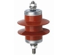
The truth about MOVs (Metal Oxide Varistors)
The truth about MOVs (Metal Oxide Varistors) 1.MOVs "wear out" with time, and should be replaced before they fail. The manufacturers of MOVs publish MOV surge degradation curves, sometimes called "lifetime ratings", or "pulse ratings"1. These curves show the number of surges that the manufacturer says their MOVs should survive at various surge levels. Mysteriously, when these very same Metal Oxide Varistors are installed in a powerline surge suppression product, it has been claimed that the MOVs do not degrade, can last 1,000 surges, etc. But curiously, the surge suppressor manufacturer seems unwilling to subject their product to an independent test lab for verification of their outrageous claims. Don't believe them. Demand to see independent proof! 2.There is no practical way to know how many surges an MOV has already intercepted and how large those surges were. 3.There is absolutely no practical way to determine how much degradation has taken place in an MOV, or how much surge life is left in the MOV. If anyone states otherwise, demand to see proof! Verify that proof with an independent, reliable source. 4.Since there is no way to tell how much life is left in an MOV, the ONLY conclusion that can be drawn, is that continued use of such a product is simply a gamble. 5.MOVs have proven to be so unpredictable, unsafe and ineffective that UL (Underwriters Laboratories, Inc.), CSA (Canadian Standards Association), and the Federal Government are all issuing strengthened specifications relating to powerline surge suppressors, all to become effective in 1996. a) UL is issuing their new UL 1449, second edition. They are attaching to that specification an optional testing service3, to allow manufacturers who want UL to certify their performance to reasonable levels of endurance in 1,000 surge increments. b) CSA is requiring all surge suppressors pass 3 surges of 6,000 volts, 3,000 amperes. A new test, with the implication being that many of the products previously would not meet even this minimum standard. c) The Federal Government has defined three grades of surge suppressor, and three classes within those grades5. A product must pass 1,000 surges as called out in the following chart to qualify for the Grade A, B, or C designation. Class 1 is a suppressed voltage rating of 330 volts. Class 2, 400 volts, and Class 3 is 500 volts. Grade A, Class 1 is the best. [View Details] -
How does an NTC Thermistor Work?
How does an NTC Thermistor Work? NTC negative temperature coefficient thermistor works NTC is Negative Temperature Coefficient of abbreviations, the meaning of a negative temperature coefficient, refers to the negative temperature coefficient of semiconductor materials or components, the so-called NTC thermistor is a negative temperature coefficient thermistor device. It is based on metal oxides, such as manganese, cobalt, nickel and copper as a main material, and the ceramic manufacturing process made. These metal oxide materials have semiconductor properties, because the conductive way completely similar germanium, silicon and other semiconductor materials. The temperature is low, the number of these oxide material carriers (electron and hole) less, so its resistance value is high; as the temperature increases, the number of carriers increases, so the resistance value is lowered. The range of variation of the NTC thermistor at room temperature 10O ~ 1000000 ohms, the temperature coefficient of -2% to -6.5%. NTC thermistor NTC thermistors are widely used for temperature measurement, temperature control, temperature compensation. NTC negative temperature coefficient thermistor NTC (Negative Temperature Coefficient) refers to the reduced resistivity exponential relationship, with a temperature rise phenomenon and material having a negative temperature coefficient thermistor. The material is sufficiently mixed with manganese, copper, silicon, cobalt, iron, nickel, zinc, and the like of two or more metal oxides, molding and sintering process is made of a semiconductor ceramic having a negative temperature coefficient, can be made (NTC) thermistor. Ratio, sintering atmosphere, sintering temperature, and the structural state of the resistivity and material constants with the material composition varies. Now also appears to the silicon carbide, selenium, tin, tantalum nitride, etc. as the representative of the non-oxide-based NTC thermistor material. Most NTC thermistor semiconductive porcelain spinel structure or other structure of oxide ceramics, having a negative temperature coefficient, the resistance value can be approximately expressed as: where RT, RT0 is the temperature T, T0 when the resistance value, Bn The material constants. Ceramic grain changes due to temperature changes in the resistivity, which is determined by the semiconductor properties. NTC negative temperature coefficient thermistor History The NTC thermistor experienced long stage. 1834, the first time scientists have found that the characteristics of the negative temperature coefficient of silver sulfide. In 1930, scientists found that the cuprous oxide - copper oxide has a negative temperature coefficient of performance and the success of the use of in aviation instrument temperature compensation circuit. Subsequently, due to the continuous development of transistor technology, thermistor made significant progress. NTC thermistor developed in 1960. NTC negative temperature coefficient thermistor temperature range Its measurement range is generally -10 ~ +300 ℃, can also be done from -200 to +10 ° C and can even be used for temperature measurement with +300 ~ +1200 ℃ environment. The negative temperature coefficient thermistor thermometer accuracy can reach 0.1 ° C temperature sensing less time to 10s. It is not only applicable to the granary thermometer, also can be used in food storage, medicine and health, scientific farming, marine, deep wells, high-altitude, glacier temperature measurement. [View Details] -
 Whatever we are doing their own thing, and it is the very basic thing is the future of SMEs must use the product. [View Details]
Search
Contact Us
Contact Person:
Miss Li MeizhenTel:
86-769-82825339- 82825369
- 18929453899
Fax:
86-769-82829959Email:
nanalee.mc@163.com
